


Disclosure: This post may contain affiliate links; if you buy through them, we may earn a commission at no extra cost to you.
As an Amazon Associate I earn from qualifying purchases.
Safety & accuracy: DIY work involves risks. Use proper PPE and follow local codes and tool manuals. Plans/measurements can vary, verify all dimensions and materials before cutting or wiring.
Safety & accuracy: DIY work involves risks. Use proper PPE and follow local codes and tool manuals. Plans/measurements can vary, verify all dimensions and materials before cutting or wiring.

Who Is The X16 Phone System For?
The X16 Phone System is a feature rich small office phone system that supports 4 incoming analog telephone lines expandable to 6 lines with an expansion card and up to 16 extensions. It is recommended for businesses with 2-10 employees.
X16 is a good system for offices that currently have their phones wired for an analog phone system or an older digital key system they would like to upgrade for more features. Some of the features available in the X16 system are:
- Caller ID and Call Waiting
- Intercom calling and paging between extensions
- Voice Mail with a general mailbox and mailbox for each extension
- Automated Receptionist with day and night modes
- Automatic call forwarding to cell phones
- 3-way conference calling
- Music-on-hold, both internal and external
You can buy the parts X16 server and X16 phones independently but it's more economical a package like the X16 4 Phone or X16 8 Phone
 bundle.
Who Is This Wiring Guide For?
This article will help you wire your X16 based phone system if you currently have Cat5 or better cable running between all your telephone jacks and a central location and would like to use 110 blocks to be able to use the existing wiring in the future so you have the option to convert to a VOIP based system.
The X16 phone system can be wired in either a star or tree topology. A star topology has all cables from the phone jacks coming to one location while a tree topology allows you to connect up to 4 phone jacks together by running cables in between jacks with only one wire for each of 4 jacks coming back to a central location. That makes the X16 system very versatile and able to be installed in a wide variety of existing settings without having to hire a professional.
The X16 phone system can be wired in either a star or tree topology. A star topology has all cables from the phone jacks coming to one location while a tree topology allows you to connect up to 4 phone jacks together by running cables in between jacks with only one wire for each of 4 jacks coming back to a central location. That makes the X16 system very versatile and able to be installed in a wide variety of existing settings without having to hire a professional.
In this article I'll be doing a star topology. With a star topology you can terminate your phone jack cables in either a 66 block or a 110 block. The manual for the X16 shows how to terminate into a 66 block. In this example I'll show you how to wire an X16 system with a 110 block.
I chose a 110 block because I think it's a little easier to understand than a 66 block for people that don't have a lot of experience with telecom wiring and also because a 110 block is easier to use for data networks in case you'd like to switch to a VOIP based system in the future. A 110 block also takes up less physical space than a 66 block which may be an issue for some.
To punch down to a 110 block you will need to already have or plan to install Cat5 or better 4 pair twisted pair cabling from your phone jacks to a central location where you'll be installing your phone system. This will also work with Cat3 cabling if that's what you already have installed but it won't support VOIP in the future.
If you're phone system isn't wired with 4 pair twisted pair wiring (white-blue, blue, white-orange, orange, white-green, white-brown, brown) and instead is wired with older style and thicker gauge 4 wire cable (red, green, black, yellow) you will be better off terminating your cables in a 66 block unless you'd like to upgrade your wiring as well.
Read my article on how to wire a 110 block if you're not familiar with telephone distribution devices.
If you'd like to use 66 blocks you can still get some good information from this guide that will help.
Example Office
We're going to wire up a phone system for a fictitious office that will have 8 incoming phone lines and 16 telephone extensions so we wire up the X16 Server to it's maximum capabilities.
Lines 1-6 will be connected to to the X16 phone system and lines 7 & 8 will be dedicated lines for 2 fax machines not connected to the X16. With the X16 you can include your fax lines in your setup so the fax line can be used for outgoing calls when the fax isn't using it but I chose to use 2 separate lines because our imaginary office has a lot of extensions which may be in use.
Our example small business will have a total of 16 X16 phones installed.
- Reception Desk
- Conference Room
- 5 Offices A-D and warehouse office
- 6 modular workstations (cubicles) 1-6
- Warehouse break room
- Next to the loading dock in the warehouse
- Data Room
There will also be 2 faxes wired independent of the X16 system. One for the warehouse and the other for the main office.
Our building might look something like this (though I should have put the data room in a more central location):

Even though we'll be installing 16 phones only 12 of those phones will be installed at dedicated workstations. Still, this is pushing the limits of what the X16 system can handle but this is to illustrate how to wire an X16 system. You can use the guide to connect less phones.
Step 1: Panel Setup
Attach a piece of 3/4" Plywood (about 24" W x 20" H) to a wall. It should be close to where all the cables running from your phone jacks come to.
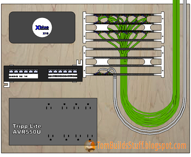

Attach 110 blocks to the plywood. For our example we're using two 100 pair 110 blocks but we could have also used 3 50 pair blocks or one 100 pair and 1 50 pair. Since we have 18 phone jacks we can keep all our phone jack cables (station cables) on one 110 block. It is good practice to keep your station cables terminated to a separate wiring block. These do sometimes need replacing or re-configuring but your jacks don't tend to move around too much.
Next mount the X16 Server to the plywood with a 12 port patch panel underneath it. The Intellinet 560269 Cat6 Patch Panel would work well here as it already comes with the mounting bracket. One thing to keep in mind is that the patch panel has RJ45 (network 8P8C) ports but we only need the smaller RJ11 (6P2C) ports used for telephones. We could get a modular patch panel and put in RJ12 keystone ports but it's going to be cheaper and easier to go with the standard RJ45 patch panel. Telephone plugs will fit into RJ45 ports but not the other way around.
Optional but recommended UPS: Attach a UPS (uninterruptable power supply aka battery backup) to the board as well. I recommend the Tripp Lite AVR550U because it serves 2 important functions.
First, it does what most small UPS's do, in the event of a power outage it will run your equipment on battery power. Second, the AVR550U is the most affordable power-strip-style UPS that has AVR (Automatic Voltage Regulation). It will protect your equipment and keep it running in the event of a brownout (under-voltage) or spike (over-voltage) in your power lines. Your phones are an important part of your business and having this type of protection is important.
If your X16 server loses power for more than a couple of minutes you will lose your voice mail setup as well as all your recorded voice mail messages. The AVR550U I believe will keep the X16 Server running on battery power for about 2 days.
In the event of a power outage you won't be able to use the X16 phones unless you have them connected to backup power as well but you will still have voice-mail for your customers to leave a message or for you to leave an outgoing message. You also won't lose your existing voice mails.
Optional but recommended External Music-On-Hold: Although the X16 has a built in music on hold feature connecting an external player like the Grace Digital GDI-USBM10 Message and Music on Hold MP3 Player gives you more control and allows you to insert custom message along with the music. The sound quality will also be better.
Optional but recommended UPS: Attach a UPS (uninterruptable power supply aka battery backup) to the board as well. I recommend the Tripp Lite AVR550U
First, it does what most small UPS's do, in the event of a power outage it will run your equipment on battery power. Second, the AVR550U is the most affordable power-strip-style UPS that has AVR (Automatic Voltage Regulation). It will protect your equipment and keep it running in the event of a brownout (under-voltage) or spike (over-voltage) in your power lines. Your phones are an important part of your business and having this type of protection is important.
If your X16 server loses power for more than a couple of minutes you will lose your voice mail setup as well as all your recorded voice mail messages. The AVR550U I believe will keep the X16 Server running on battery power for about 2 days.
In the event of a power outage you won't be able to use the X16 phones unless you have them connected to backup power as well but you will still have voice-mail for your customers to leave a message or for you to leave an outgoing message. You also won't lose your existing voice mails.
Optional but recommended External Music-On-Hold: Although the X16 has a built in music on hold feature connecting an external player like the Grace Digital GDI-USBM10 Message and Music on Hold MP3 Player
Step 2: Punch Down Station Wires
In the example we have a total of 18 phone jacks. Cat5e cable is run from each jack (green) to our telecom closet next to where we installed the mounting board.
Run the cable up from under the 110 blocks and start to punch them down on the top 3 rows of the 110 blocks. Leave a little loop of cable (as shown in illustration above) in case you ever need to re-terminate the cable in the future.
Cat5e 4 cable has 4 pairs of wires. Each wire gets punched down between the plastic posts on the base of the 110 block. The order of wires is white-blue, blue, white-orange, orange, white-green, green, white-brown and brown.

Continue punching down all your station wires.

Your cables should be labeled so you know which jack they connect to. After you've punched down all your station cables, insert the 110 cover, labels and punch down the 4-Pair C-Clips over the cables you punched down.

Step 3: Incoming Lines
In this example we have a total of 8 incoming lines. Six will be used with the X16 server for phones and 2 will be used for fax machines. The phone lines come in on 2 Cat5e 4-pair cables (grey) from the NID (network interface device) and carry 4 lines each.
We'll punch these down to the bottom row of our 110 blocks in the same white-blue, blue, white-orange, orange, white-green, green, white-brown and brown order as usual. Remember, blue is line 1, orange is line 2, green is line 3 and brown is line 4 in each cable.

Step 4: Connect Patch Panel to 110 Blocks
The patch panel isn't required but it is recommended. The other option is to punch cables to the 110 block then terminate them with RJ12 connectors on the other end but I think it's generally a bad idea to do this.
By using patch panels the connecting cables stay fixed to the plywood so that they're more secure and less prone to mechanical failure. It's a pain to have to remove a wire from a 110 block and punch it down again so this can reduce maintenance. If a connection goes bad it will most likely be in the patch cord which is easy to replace.
We're going to be running 3 Cat5e cables between the patch panel and the 110 blocks. One will be for the Extension wires, the other two will be for the cables that connect to the incoming phone lines.
The extensions cable should be punched down on the start of an empty row and the rest of that row should be left empty for now.
The other 2 cables should be punched down somewhere near the incoming phone lines. I chose to punch them down on the row abovethe incoming lines.

On the other end of the cables, where they connect to the patch panel, we're going to do something different. Instead of punching all 8 wires to one 110 IDC we're going to split the pairs so that there's one pair for each port. Each pair will be punched down to the blue pair on the patch panel port.
I thought it would be easier to demonstrate it using keystone jacks so you can see how it will be wired.

Since we only have 6 incoming lines connected to the X16 (the most it can handle with the extension card), on the second incoming line we only need to punch down 2 pairs (blue and orange) for lines 5 and 6.
After the patch panel is punched down we can connect telephone line cords with RJ11 connectors on each end between the patch panel and the corresponding ports on the X16 server to feed the incoming 6 telephone lines and send the 4 extension pairs to the 110 block.

Step 5: Extension Bridge
The X16 server has 4 pairs of wires coming out for connecting extensions. Each pair can have 4 phones connected to it (for a total of 16 extensions) in series or in parallel. We have all our jacks coming to one location and will be connecting them in parallel.
XBlue sells a 4 Port Network Connector (XB1698-XB) to connect 4 phones to one of their extension ports but we're going to be creating a bridge in the 110 block to serve the same purpose. Making the splits on the 110 block is a cleaner installation that is easier to maintain.
On the same row of the 110 block where we punched down the extension cable we're going to create 4 bridges (one for each extension port) that will allow us to connect 4 extensions. You'll need to have a non-cutting 110 punch down blade to create the bridge in addition to the cutting blade.
Note: Even if you're setting up your system with less than the 16 extensions that I am in this example punch down the bridge exactly the same way so you can expand easily in the future.
Start with the blue pair for extensions 1-4. Punch the first pair down next to where you punched down the extension cable then skip over 7 posts then loop up and down the next 4 sets of posts as shown below.

Repeat for the remaining 3 pairs using a corresponding color of cross connect wire to match the extension pair. They sell spools of cross connect wire (like this General Cable 2114211 4 Pair Cross Connect Wire ) which has white/blue, white/orange, white/green and white/brown pairs) but you can also just strip the jacket off some Cat5e cable. If you have a lot of phones like in our example buying the cross-connect wire will save a lot of time stripping cable and likely money too while reducing the risk of accidentally nicking the wires when stripping.

To make it easier to illustrate I'm depicting the pairs as untwisted but when you're doing the wiring only untwist as much of the pairs as necessary (no more than 1/2") to punch them down. Keep the rest twisted.
After punching down the bridges attach the cover, labels and punch down the 4 pair C-Clips. Each pair is a separate extension so label it accordingly as shown.

While we're at it we can label and add C-Clips over the incoming lines and the cables that lead to the patch panel since we're now done punching down wires to the base of the 110 blocks.

On the same row of the 110 block where we punched down the extension cable we're going to create 4 bridges (one for each extension port) that will allow us to connect 4 extensions. You'll need to have a non-cutting 110 punch down blade to create the bridge in addition to the cutting blade.
Note: Even if you're setting up your system with less than the 16 extensions that I am in this example punch down the bridge exactly the same way so you can expand easily in the future.
Start with the blue pair for extensions 1-4. Punch the first pair down next to where you punched down the extension cable then skip over 7 posts then loop up and down the next 4 sets of posts as shown below.

Repeat for the remaining 3 pairs using a corresponding color of cross connect wire to match the extension pair. They sell spools of cross connect wire (like this General Cable 2114211 4 Pair Cross Connect Wire

To make it easier to illustrate I'm depicting the pairs as untwisted but when you're doing the wiring only untwist as much of the pairs as necessary (no more than 1/2") to punch them down. Keep the rest twisted.
After punching down the bridges attach the cover, labels and punch down the 4 pair C-Clips. Each pair is a separate extension so label it accordingly as shown.

While we're at it we can label and add C-Clips over the incoming lines and the cables that lead to the patch panel since we're now done punching down wires to the base of the 110 blocks.

Step 6: Bridge Cross Connects
Now we need to create cross connections to distribute various signals. We're going to start with 4 pairs of cross connects that connect our extension bridges to the extension lines coming out of the X16. It's simply a matter of running a pair of cross connect wires from each line of the X16 Exts C-Clip to the Ext Bridge C-Clip. We'll start with the blue pair for lines 1-4.

We can now connect 4 phones to the X16 server, lines 1-4 or extensions 301-304, but before we do that let's connect the rest of the bridge.

Remember to keep the cross connect pairs twisted.
Step 7: Fax Cross Connects
We have two jacks that have fax machines connected to them that are not connected to the X16 server. Each fax will be served from a dedicated telephone line. Lines 7 & 8 are reserved for the faxes.
To feed a line's signal to a device we need to run a pair of cross-connect wires between the C-Clip of that line to the blue pair of the device. Blue since each device is only getting one line. In our case we have a cross connect going from the green pair of the second incoming line going to Fax and the brown pair of that second cable going to the blue post for the warehouse fax.

Step 8: Incoming to X16 CO Cross Connects
The other 6 incoming phone lines will be connected to the X16 server. These 6 lines will be used for our voice telephone network. It will allow us to make and receive calls with the outside world.
To connect cross-connect wire between the incoming line's C-Clip to the X16 In C-Clips. We'll start with line 1 which is blue to blue.

Then continue with the remaining 5 lines.

Step 9: Extension Cross Connects
The X16 Server is now connected to the phone company. All we have to do is jumper the X16 extensions to the jacks where we want those extensions to be. There's one important thing to consider though.
If you wired a jack but have not installed a phone on that jack (empty office for future use) do not attach cross connect wires between that extension and jack. If there is a long length of cable connected to an extension without a phone on the other end it can cause noise in the phone system.
In the future if people switch offices it's easy to rewire their extension. Just remove the existing cross connect wires and punch them down to the new location.
In the future if people switch offices it's easy to rewire their extension. Just remove the existing cross connect wires and punch them down to the new location.
Before we start wiring up extensions I think it's worth noting that it's common practice to use a different color of cross connect wire (ex blue/yellow like this General Cable Cross-Connect Wire in Blue/Yellow ) to identify types of devices such as digital phones but for smaller installations like this I don't think it's that big a deal if you don't want to buy the extra wire and just use the cross connect wire you already have.
Reception - 301
We're going to start by connecting the receptionist's phone to extension 301 on our extensions bridge. The first phone you connect to the system automatically gets provisioned to extension 301.
All we need to do is punch down a pair of cross connect wire to the 301 Bridge to the blue pair on the Receptionist C-Clip, routing it neatly around the 110 blocks.

Extensions 302-304
Now we'll hookup the warehouse phones to the other 3 extensions on the first extension line from the X16 server, remembering to punch down to the blue pair on the jack's C-Clip.
Extensions 305-308

Extensions 309-312

Extensions 313-316
Finally extensions 313-316 for Offices A through D.
The X16 Phone system is now completely wired. Here's an overview.


You are so awesome for posting things like this! In my profession people take advantage and charge me over double what they charge other people. Thanks for posting this so I can do it myself.
ReplyDeleteThe only question I have is if I have 3 lines coming into my building and a fourth which will be a dedicated fax line (like you already showed how to do), what RJ plugs would I use to get the 3 lines to all phones on my system? RJ11 as I understand only used 4 wires, RJ12 uses 6, but I actually installed RJ25 because it said it does 3 lines. Should have I used another one instead of RJ25? Thanks so much in advance!