


Disclosure: This post may contain affiliate links; if you buy through them, we may earn a commission at no extra cost to you.
As an Amazon Associate I earn from qualifying purchases.
Safety & accuracy: DIY work involves risks. Use proper PPE and follow local codes and tool manuals. Plans/measurements can vary, verify all dimensions and materials before cutting or wiring.
Safety & accuracy: DIY work involves risks. Use proper PPE and follow local codes and tool manuals. Plans/measurements can vary, verify all dimensions and materials before cutting or wiring.

If you don't have a 110 block you may have a 66 block in your home. Phone companies can charge a monthly inside wire maintenance fee if you want them to repair any issues that may occur with the phone wires inside your home. If you learn to maintain your own phone system you can save a decent amount of money. For me it's about $120 every year.
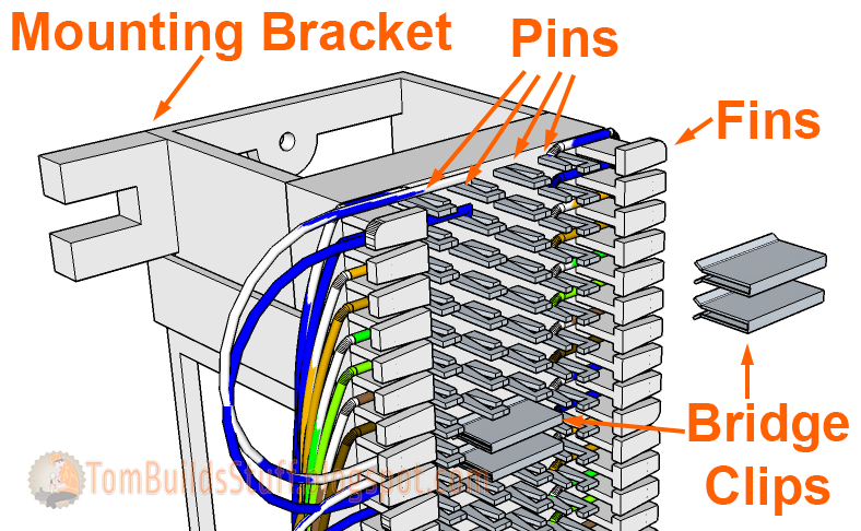
66 Block Components
There are different types of 66 blocks. The most commonly used is the 50 pair Split 66 Block.

The 66 block is normally mounted on an 89D Mounting Bracket to provide some clearance to run cables behind the 66 block.

Pins in the center of the block are were wires get connected. On a split 66 block there are 4 pins on each row. The first 2 pins on a row are electronically connected, as are the last 2 pins on a row but the 4 are independent of each other. If you connect a wire to pins 1 and 2 the signal from the wire on pin 1 will also flow to the wire on pin 2 but not to pins 3 and 4.

If you want the signal from pins 1 & 2 to flow to pins 3 & 4 you would install a metal bridge clip over pins 2 & 3.
They're normally mounted vertically but to fit larger illustrations in this article I'm going to be showing them in a horizontal orientation.

A 50 Pair split 66 block will have 25 rows of pins which allow you to punch down 50 pairs of wires, 25 on each side. With old style 4 pair (green, red, black, yellow) telephone wire you can punch down 12 cables on each side. With newer style Cat5e wire (white-blue, blue, white-orange, orange, white-green, green, white-brown, brown) you can punch down 6 cables per side.
Fins on the sides of the 66 block are meant to keep wires separated from each other. Some of the fins are slightly rounded to help you identify every 10th wire. You can write on the fin with a permanent marker or apply labels to them for identification.
66 Block Vs 110 Block
66 blocks are older style wiring blocks for telephone wiring but many telecom installers still prefer them. They're more durable which allows them to be punched down multiple times and are able to handle thicker wires that may be present in older installations.
I personally prefer the 110 blocks. They serve the same function but take up less space. 110 blocks are also more compatible with high speed networking which can save a lot of time if you want to upgrade to VOIP phones in the future.
Durability isn't an issue for me because neither should really be reused and I like that the connections in a 110 block are in the C-Clips instead of on the base so if the connector goes bad you just replace the C-Clip, you don't have to always replace the whole block as you would in a 66 block.
Step 1: Installation

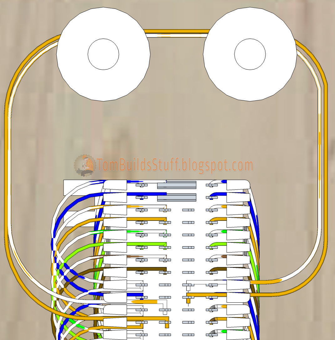
66 blocks are typically screwed to a mounting board which can be a simple sheet of plywood. Above the 66 block, 2 wiring spools (mushrooms) are also installed to neatly route cross connect wires from one side to the other or between blocks if multiple are installed.
Step 2: Punch Down Incoming Phone Lines
The cable coming from your phone company could be a 4 conductor (red, green, black, yellow) cable that supports 2 phone lines or it may be a Cat3, Cat5 or Cat5e cable with 3 or 4 pairs of wires, each pair supporting 1 phone line.
All cables should come up through the bottom of the 66 block and then pulled out the side.
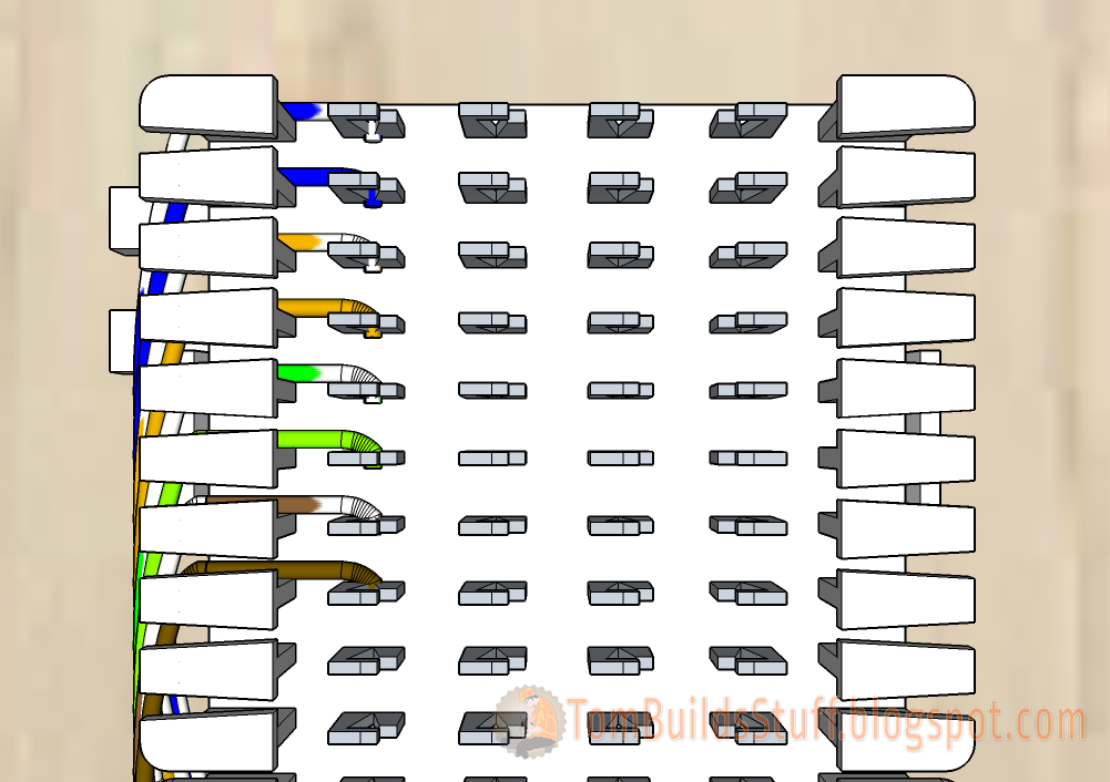
On a 66 block incoming wires are typically punched down on the left side of the block starting from the top.
Each wire is punched down to the first pin in a row with one wire per row. The order of the pairs is blue, orange, green and brown with the white wire from the pair being punched down on top. That's white-blue, blue, white-orange, orange, white-green, green, white-brown and brown.
Untwist each pair only as much as you need, pass it through a fin then hook it onto a pin from the top down. After you have all the wires from a cable on the pins, punch them down using a punch down tool with a 66 blade.
Step 3: Punch Down Phone Jack Cables
Now it's time to connect our premise wiring, the cables that run from our distribution point to the phone jacks throughout the house. These cables will be punched down on the right hand side of the 66 block using Cat5e cable. Each cable is going to use 8 pins and the order of the wires is again going to be blue pair, orange pair, green pair, brown pair with the white wire of each pair on top. Even though you may not use 4 lines in each cable it's still good practice to punch them all down.

I've highlighted the different cables with an orange box to make it easy to see in the illustration. Each cable will run to a different jack to allow one phone to be connected to it.
Step 4: Create Incoming Lines Daisy Chains
Right now our incoming lines aren't connected to any of the phone jacks since we're using a split 66 block. There are a number of ways to send the signal to each jack but the preferred method is to use cross connect wires to duplicate the signal to other pins on the left side of the block. This allows you to use bridge clips when you want to send a particular line to a phone.
We'll start with the blue pair, line 1.

Start by attaching the wires to the second pins where you punched down the incoming phone lines (left in illustration) then loop the cross-connect wires and and out of the fins so you can hook them around every 8th pair of pins as shown.
Keep the twists in the cross-connect wires as much as you can. For the illustration they're untwisted for clarity.
When you punch down the cross connects you'll need to switch to a non-cutting 66-blade in your punch down tool so you don't trim the wires when you're creating the daisy chain above.

If you have multiple incoming phone lines, repeat the daisy chain process for each line or all the punched down wires so you have them if you need them.
Step 6: Attach Bridge Clips
The jacks still aren't connected to the incoming lines but we'll do that right now.
In our example we want to send line 1 to all of our phone jacks. To do so all we need to do is insert a bridge clip between pins 2 & 3 for all the blue pair wires.

Each phone is now connected to line 1 from the phone company.
If you want to connect other lines to phones, insert a pair of bridge clips to the corresponding pair of wires.
Step 7: Alternate Cross Connect Method
Using bridge clips is the best method but sometimes you may want to do something a little different like have incoming line 2 be the line that a phone sees as line 2.
For example you have a home office and you only want your office phone line to be connected to that phone. Instead of using bridge clips you'll use cross connect wires coming out of the left side connected to pins 2 of an orange pair, looping around the top of the mushrooms and then punched down to pins 3 of the blue pair that leads to your office phone.
If our office phone was the second cable on the right, instead of using bridge clips our cross connect would look something like this.


Wow, those are beautiful diagrams. They must have taken a while to draw. Excellent explanations. I don't come from an electrician background, but I do know lots about electronics. Just a bit more theory at the top would make understanding the rest of the article easier. For instance, at heart, this is just 50 pairs of pins connected together, and you are showing different strategies for making use of those 50 pairs of tie points. If that was stated at the very top, I could follow the rest better. Thanks!
ReplyDeleteThank you. I explained in the first section on 66 Block Components how there are 25 rows with 2 pairs of connected pins on each row. What would you suggest I do to make it clearer?
DeleteI want to know something ..how can I connect the commutator?
ReplyDeleteI dont know where do I have to connect ..because this phone wont turn on.. the model is KX-T7730.. i dont really undesrtand where is located...
can make a diagram? please.. answer me... i need really help...
The Panasonic KX-T7730 is a digital phone and cannot be used as a stand alone phone. You need to use it along with one of Panasonic's PBX systems like the KX-TA824. See http://amzn.to/1MsE8W1 for more info. It will work with other Panasonic Hybrid PBX systems as well. It's a small PBX system designed for home use or small offices. Do you have one of Panasonic Hybrid PBX control units? If not the phone won't work.
DeleteOh, I understand now...
DeleteActually.. after many days trying to connect dirtecly to phone sytem KX-TA616.. on the J01 "pum" the phone was alive again.. but after 5 hours of "8bit music", i pushed number 1 and phone could stay quite...
i dont really understand how happened this.. nut now it is working... i think it is a miracle..
can you help me guiding me with some diagram of the connections?.. because idont understand how much important is it "88block" or "110block" i have connected directly the phone to the system phone and it is working until now...
I need something like: "phone" - "rj42 to central phone" - "c1 to external line"... im not sure how can i connect those thing..
sorry for my english im from ecuador on south america.. and i cant find information of this stuffs on my language.. and you are really good in those things.
thanks.. i aprecciate your help.
This and your 110 block page are fantastic. Thank you
ReplyDeleteThis is by far the best explanation of how to wire these and the 110 blocks I found. Very detailed. I tip my hat to you sir.
ReplyDeleteThank you for taking the time to show your appreciation.
DeleteExcellent article. Appreciate it very much.
ReplyDeleteGreat article, excellent illustrations! Thank you for taking the time to put this together!
ReplyDeleteIn step 7 where you say "have incoming line 2 be the line that a phone sees as line 2", do you mean to say 'have incoming line 2 be the line that a phone sees as line 1'?
ReplyDeleteThis post might have been done a long time ago, but it just saved me a fortune on our phone system install. Our original phone guy retired and now it's up to me to figure out how to do this and now I have a clear understanding of how it all works and how to correctly wire the system. Thank you so much.
ReplyDeleteThanks for posting this. I too am now in charge of a phone system that I barely know but need to learn! I am having trouble with the color scheme. My 66 block looks different than this. I have 7 phone lines connected to it and three of them are currently down. It starts on the left side with colors: Ow, O, Gw, G, Bw, B, Brwn/white, Brown. And then it runs another cat5 cable beginning with O, oW, wB, B, Brown/White, and then brown. I have no idea why the person before me skipped Green and Gw.
ReplyDeleteSomehow the orange/oW is paired with a phone line Green/red and it's working. If I could attach a picture it may be easier to understand. I hope I'm making sense, but I cannot figure out why he did this and how Orange/Ow pairs with red/green phone line. I want to use all cat5 cables on this 66 block without messing any current connection up.
Electrons don't care what color the insulation is. They'll pass through the wires just fine. :) They're just there to make it easy for us to understand what's going on. Since you only mentioned green and red incoming wires I guess the previous person maybe didn't care too much about the other two lines since you only have one line? Still sloppy.
DeleteBell - Blue
DeleteOperators - Orange
Give - Green
Better - Brown
Service - [Slate]
Big - Blue
DeleteOle - Orange
Gorilla - Green
Breath - Brown
Stinks - Slate
If you were a woman I'd marry you, this was exactly what I was looking for. Got an office where Line 1 went to one jack and Line 2 went to another and didn't want to have to pay someone $$$ for something that I should be able to do with my punch down tool and little effort. You are a saint and a scholar.
ReplyDeleteI'm attempting to condense lines at a few businesses. Currently we pay for 4-6 phone lines. 1 line for voice, everything else for random equipment. (Fax, EBT, etc). I'd like to condense to 2 lines. Line 1 (voice) in + out will stay the same, everything else should connect back to line 2.
ReplyDeleteI should be able to Daisy chain Line 2 like you described, then move the old line 3,4,5,6 jacks to one of these new daisy chained Line 2s Correct? Or is there a simpler way to accomplish this?
Hi Tim,
DeleteI believe you can do that. It's a little hard to picture.
I think what I would do is punch down the lines that go to the equipment in a standard way. If you're using cat3 or cat5 cabling you'd have 4 pairs. The standard is to punch down all 4 pairs (8 wires) of the line which would mean you'd have room for 6 extensions on each side of the block.
You could also just punch down 2 pairs, one for the pair you're using and possibly a 2nd just for future expansion. Or you could just do one pair but if you require additional lines at an extension in the future it would require more rewiring.
Then, with only 2 pairs you'd daisy chain one side like I showed but with only 2 lines (2 pairs). You can use bridge clips for the main phone line where line 1 goes to line 1 at the phone. For the data devices you'd use cross connect wires to go from incoming line 2 to the extension line 1.
You may need an extra 66 block if you punch down all 4 pairs on both incoming and premise wiring lines. Sounds like a small installation so the cost of the second block might be worth it to make it easier to expand or make changes in the future if necessary.
I hope that helps.
Hi Tom,
ReplyDeleteCan you please also include how to connect the 110 Blocks to into PBX TDE600 System with digital and analog phone connections.
regards,
Franz
Hi Franz,
DeleteNot very likely to include that. I don't own one of those systems or have a need to purchase one. I did do the X16 phone system wiring because it looked neat and could be used in residential. That might help you out. Most pbx systems you'll use 66 or 110 blocks to terminate the premise (extension) wiring from the phones to your telecom closet. Then you'd use cross connects to go from the wiring block to the PBX. That's a pretty complicated system you have though with SIP, Virtual, digital, cell, and a whole bunch of other features. Seems pretty cool thought but the instructions look pretty detailed.
Awesome diagram and thanks for posting. Can u describe a bit about the other end, namely the jacks the phones plugs into in each office for instance. I'm going to wire rj45 with 568b. Will this change anything in your 66 block diagram? Thanks again
ReplyDeleteJoe
Extremely detailed and helpful. Thank you very much.
ReplyDeleteI must wholeheartedly thank you for finally clearing up wiring a 66 block. For years I have avoided jobs using them because I just didn't get it. I just couldn't wrap my head around how it actually worked.
ReplyDeleteBut after reading or rather studying your article for the past hour, the fog has lifted. I GET IT NOW!!!
I have a new found confidence to go buy a couple blocks or use the old one in my basement to try and set up a few different scenarios that I might encounter or have to install as practice.
You truly fit the definition of teacher. I take my hat off to you Sir.
In the first two pics, you attached line one to the lower most pins. In the second two pics, you attached line one to the inner pins. Please clarify
ReplyDeleteI'm not sure which images you're referring to. In the first picture that has wires there are the incoming wires punched down to the outer pins then I started the cross connect daisy chain on the inner pins. That's generally how I do it, punch down premise to outer, cross connects to inner except for this example I continued the daisy chain on the outer since I didn't punch down premise wiring on one said in this case.
DeleteI also posted a more recent version of a different version of 66 block wiring that you might want to check out.
Does that clarify things?
Hi Tom,
ReplyDeleteI have a single line with a new 66 block, with four jacks. With Cat 5. Long story..... I do have dial tone to the outside of the house. I want to rewire the new 66 block. I did just buy a fluke toner. So I need help where to start before I start ripping wires and my hair out.
thanks Jerry
truegritt25@hotmail.com
Hi Tom,
ReplyDeleteThis by far the best explanation I have found on this topic. Thank you so much for sharing your knowledge.
Best regards,
-Carl
Hi Tom
ReplyDeleteThanks for an excellent tutorial! Using a 66 block for our Valcom paging system and this is an awesome how-to for understanding the layout!
Thanks again
Jim T
Hi Tom,
ReplyDeleteLike all the others, I wanted to say "thanks" for taking the time to share your knowledge. I also wanted to confirm that a "hub" like the 66 block is for telephone whereas a "switch" should be used for Ethernet/computer connections. I recently moved to a house where the builders used CAT5 wiring for telephone and ethernet wallplates with all the wires coming together at a 66 block. I'm going through the process of identifying the wires that I need for ethernet and removing them from the 66 block.
Thanks again.
Thanks Tom, I, too, have avoided a lot of 66 block wiring jobs because of my general misunderstanding of how it is wired...actually, lack of confidence...I think I knew how they were wired. You just reinforced what I thought all along and now I am much more confident that I can install and/or repair wiring now.
ReplyDeleteHi Tom,
ReplyDeleteSo I moved into an apartment and Im trying to run internet, I changed all the phone lines to Cat5e but nothing was communicating. I opened the phone box and it looked like a bomb went off, only the orange wires are connected and the run all over the place, nothing like this diagram. Help. Can email me at doktrulok@gmail.com
66 block for phone... 110 block for photo or data but it's probably best to go directly to a patch panel with RJ45 on the front and 110 blocks on the back.
Delete110 block wiring: https://tombuildsstuff.blogspot.com/2015/02/how-to-wire-110-block-telephone.html
Ahh, I get it...
ReplyDeleteYou wrote and defined a row, "Pins in the center of the block are were wires get connected. On a split 66 block there are 4 pins on each row." This was supported by your diagram illustrating pins 1 and 2 are electrically connected, as are pins 3 and 4, but pins 1 and 2 are not connected to pins 3 and 4.
In describing a block's capacity, you wrote, "A 50 Pair split 66 block will have 25 rows of pins which allow you to punch down 50 pairs of wires, 25 on each side." "25 rows of pins" on a side, led me to think that side can support only 12 pair... so two sides can support 24 pair.
In actuality, a side has 50 "rows" of pins, supporting 25 pairs. Then x 2 sides equals 50 pair.
I know I misunderstood your definitions, so others might too.
I want to compliment you for the great article. I have 30 years experience in telephony and networking, and your article was clear and on point. Just one minor edit change were to where in "Pins in the center of the block are were wires get connected." Thanks again for a great article.
ReplyDeleteThanks and it all makes sense.
ReplyDeleteI walk to my closet. Six pins per row.....DAMMIT!
And it has 12 rows? That's similar in concept but it's not a split block like this. I believe all the pins on the tie are connected. You can punch down 6 pairs and connect them to 5 extensions. Those tires of split block were common in residential applications.
DeleteI still dont understand the point to these. What do they do? Are you merging lines? What is the purpose of these?
ReplyDeleteWhen you get phone service from the phone company, or even from your online provider, you only have one physical phone line coming in. In most homes you'll want to have phone jacks in multiple rooms. This device (as well as the 110 wiring block) allows you to distribute the phone line to multiple locations.
DeleteYou could just wire from one device to the next but this allows you to have an individual line from each jack coming back to one central location which makes maintaining the phone lines easier should something go wrong or if you want to make changes in the future.
Hi Tom. Made everything seems easier by the way you explained. I have a freidn that just did his basement so before anything happened I ran cat5 all over and installed jacks at different points in his basement since his modem is all the way upstairs. He has Verizone Fios, How do I give him hardwired internet to all the connections I made? He already bought a small netgear switch. Thanks.
ReplyDeletePunch all the cables to an RJ45 patch panel. Then use patch cords to go between the patch panel and the switch.
DeleteHave a look at the video in this post. It's about testing coax but on the bottom of my structured wiring panel you can see my 1u RJ45 patch panel and the blue patch cords going down to my network switch. https://tombuildsstuff.blogspot.com/2018/11/how-to-test-and-locate-coax-cables.html
You'll need a 110 blade to punch those down.
also check out my other posts on structured wiring
Great tutorial moved into a new house and the phone lines are a complete mess and consist of old 4pair wires, cat3, and cat5e. I guess the house has been rewired a few times but each time the lines only went to specific parts of the house. This will hopefully help me to consolidate this mess and allow me to tear out the old wire so the basement looks a lot better..thanks..only thing I wanted to ask is about the incoming lines..how can I get another line to come in from the NID outside? Or can I split that Bw B pair into more lines to go to other parts so I can wire the Ethernet cable to other rooms where they will end at rj 45 Jack's in the wall. In the NID it looks like only Blue pair is connected.. do u have to pay for another line to get the Orange pair to come into the house?
ReplyDeleteThank you.
DeleteEach pair is a line. If you want another line (with it's own dialtone) you need to pay your telephone provider for it if you want to have more than one phone call at a time. The 66 block essentially works like a splitter, splitting the incoming signal to each extension but you can only make one call at a time.
I start learning about networking and I love watching yt video where specialist redesign network in a company, but up to now I couldn't find good information about what is this 66block and how it is work.
ReplyDeleteSo many thanks to you for these explanations. Great work :D
W
ReplyDeleteYou flag Videos on Youtube that have no copyright just to grab their email addresses when a dispute is open. Very unethical, Have reported. What a scammer!
ReplyDeleteYou reported a copyright infringement because a tour of a 66 block? Yeah - reported.
If you get the kind of 66 block with the 50 pin Amphenol connector on it, you can get "harmonica adapters" [Google "258A Harmonica"], which will bring out the wiring to 6 RJ45 jacks (make sure to get the 568B or 568A version to match your wall jack wiring -- I'm a 568B kind of guy).
ReplyDeleteWire the wall jacks to one side of the 66 block and plug the harmonica adapter into the 50 pin connector. Plug your RJ jumpers into the harmonica adapter and thence to your network switch.
Thank you so much for your generous article. Very informative and the illustrations are the best I've seen. Thank you again.
ReplyDeleteHey brother have you made any videos on this? Got a little confused when I saw the extra wires.
ReplyDeleteAmazing post. Thank you for all of your time in putting these great diagrams together. It was very easy to follow the 66 block setup. Even in 2022 I am trying to do this in my house. I appreciate your thorough explanation. I looked on YouTube and nothing was as easy to follow as your diagrams.
ReplyDeleteThank you for the great write-up. Here we are about 9 years after you took the time to share all of this information. It's helped me greatly understand an older system that has been gutted and redone more than a few times over the last 3 decades. I knew there was a way to make the system we have in place better and more updated, but I didn't have the understanding needed to make the changes.
ReplyDeleteAfter carefully planning the necessary changes to simplify our system, it was a success without any issues.
Hope all is well and thank you again for the information.
Glad I could help!
DeleteI'm in progress of taking over the valcom analog speaker infrastructure at my school which is wired into.many of these 66 blocks. the mess of wires is ridiculous and I'm not really sure what I'm looking at. pictures are of the wiring mess
ReplyDeletehttps://photos.app.goo.gl/TqfYzUynWbFUp6bX7
This is great. Our Panasonic PBX at church was damaged in a lightning strike and I'm helping install a new system. Looking at the tangled web of spaghetti was intimidating. This will help me tremendously as I get the new system, which will mostly use WIFI, up and running. We have three phone lines, one POTS and two U-Verse voice AKA AT&T Phone. Thank you so much.
ReplyDeleteThis is very helpful as I diagnose and troubleshoot our three active phone lines, plus two inactive lines, serving 20 extension phones and one door intercom. We had a lightning that degraded our PBX. I'm a volunteer and this the situation at our church and school.
ReplyDelete